A Simple Power Shutdown Circuit
for the Raspberry Pi 2/3
Introduction
Often I hear node owners ask if there is a way to shutdown the Pi gracefully with a button or switch. Linux or any other OS for that matter should be shutdown gracefully and not just with a pull of the power. We addressed this in the Pi halt switch howto many years ago. It is a simple push button switch that if held down for 5 seconds initiates a graceful shutdown of the Pi. However this method does not remove power from the Pi or the radio.
Scan forward a few years and we now have a large number of Allstar users that are operating portable and mobile nodes connected to wireless hotspots. This has developed a whole new desire to make the shutdown process more automatic. With the new hamvoip DNS node lookup code users can enter their car turn on their node and after boot instantly be connected to a destination node. This makes it very easy to treat the hotspot connected node much like an RF radio. The problem arises when you need to leave your node perhaps for 5 minutes or maybe an hour or more. If you want to turn it off when leaving one option would be to install the simple halt switch mentioned above and push it before turning the car off and leaving. But what if you are in a hurry and forget to do that or you just don't want to take the time to push a button to shut it down. Maybe the node is located back in the trunk and not that accessible. Just shutting down the Pi will usually not cause a problem but it is never a good idea and eventually you could corrupt and lose your system when you need it the most.
The circuit described here should eliminate all of these problems. It automatically shuts down the Pi and node radio when you leave the car or turn off the node with a power switch. In its simplest form all you have to do is turn the ignition off in the car and leave. When you return the pi will boot back up and make your outbound connection all without operator intervention. A couple of alternative circuits are described with and without a small backup battery.
How it works
First I will describe the on/off switch method that would work like an on/off switch on a radio. You could install the switch on your portable node box. Using this method the node and radio need to be powered from an always on source, a power supply or battery. In the case of a car it would be connected to a +12V source not switched when the ignition is turned off. When you turn on the switch the Pi and radio receive power, the Pi boots and sets a GPIO bit to keep the power on. It then monitors the power good bit. If the switched power is turned off it initiates the shutdown process, informs the user the system is going down via the radio, and shuts all power down to both the Pi and the node radio.
So what if you don't want to connect the node to always on power and you do not want to physically throw a switch to power down your node? In this case the node would be connected to switched power which is usually always the case when powering from a "cigarette plug" connection in a car. In this case some means of powering the system is required for the short shutdown period. Depending on the power requirements of the radio the power switching (MOSFET or relay and Schottky diodes) need to be sized accordingly. For this article we will assume a low power (~1W) node radio like a Baofeng 888 or UV82 in low power and the Pi. When the user turns on the car the radio and Pi receive power, the Pi boots and sets a bit to keep the power on. It then monitors the power good bit and when the power to the node is removed (the car is turned off) the shutdown is initiated after a short delay, the user is informed and all power is shut off. The amount of time the battery is required to supply power is about 10 seconds during this shutdown period. In our tests using the Baofeng 888 in a node where two high efficiency supplies provide power to the Pi (5V) and the 888 (3.7V) a 9 volt NiMH rechargeable battery seems to work fine. The batter is trickle charged during the powered period.
When the pi shutdown process is started the Pi's green LED will flash faster and then go out. After the shutdown wait period power will be removed and the red led will also extinguish.
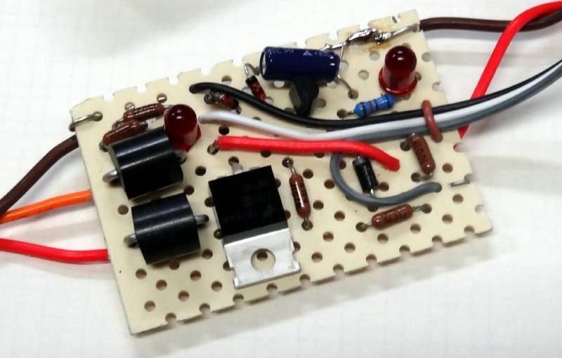
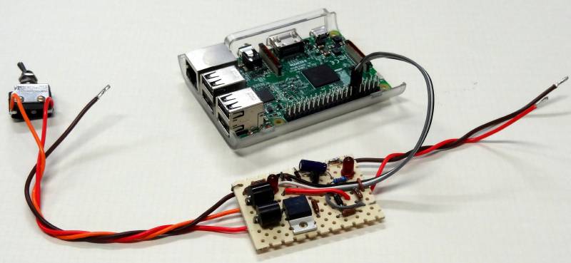
Breadboard prototype
The wiring to the left, source power - Brown (gnd), Red (Always on +12), orange (Switched +12), to the right, power to radio and Pi supplies - Brown (gnd), Red (+12), Control wires - Black (gnd), White (power good), Gray (Power shutdown)
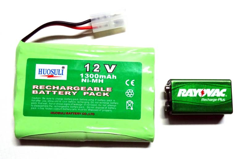
12V 1300mAhr and 9V 200mAhr NiMH backup batteries
The 9V battery works fine for the Baofeng 888, the Baofeng UV82 and other
higher voltage/power radios should use the larger 12V battery pack
Building the circuit
The circuit is rather simple and could be fabricated on a perf board as shown above. We are looking into making a PC board which would make it easier to assemble. Using the printed circuit approach the board could also be make smaller. There are three wires to the Pi. Make sure these are connected on the right pins. A detailed photo is shown below. The ground pin (black in this case) is connected to pin 9, the 5th pin from the SD card end toward the inside of the board. The power good pin (white) is connected to pin 11 (GPIO0) the next pin. The shutdown wire (gray) is connected to pin 12 (GPIO1) adjacent to pin 11. See the schematic link below.
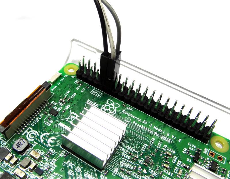
These two sites show different naming schemes for some of the GPIO pins. I use the wiringpi scheme in this article which is the default for the gpio command. You can also type "gpio readall" at the Linux prompt to see the pins and their states. While this circuit if properly wired does not supply any voltage to the Pi pins remember that the Pi GPIO is 3V logic and no voltage higher than that should be applied to any pin or damage to the Pi will result.
Software
Software is included in the hamvoip Pi edition of Allstar. Simply set SHUTDOWN_MONITOR="enabled" in /usr/local/etc/allstar.env The default setting is "disabled" The script will be loaded and run in the background at each boot. This is the same script that is used for the single button shutdown and has been modified to support both the single button and this circuit. Although we don't recommend using the script without the circuit attached the pi will operate normally in that case unless a 5 second low signal is applied to pin 11 which would cause the Pi to shutdown.
When using this circuit and script the user can still use the manual SSH or DTMF shutdown commands and the shutdown process will be the same. After shutdown the power will be removed.
Additional Notes
The circuit is not limited to portable or car installations. You could implement it just as easily at a fixed location, perhaps a location where you do not have backup power.
The circuit could control a higher power radio along with the Pi by using Schottky diodes, a MOSFET (possibly heat sinked), and a backup battery large enough to handle the load.
Batteries do not usually come charged so if you use a battery you must fully charge it before deploying. Once fully charged the amount of usage during shutdown is minimal and as long as the on "trickle time" is long enough it should work well. If you do a lot of shutdowns and the on time is short you would have to up the trickle charge current by paralleling the trickle charge resistor and LED with an appropriate resistor. At no time should the battery get more than slightly warm. Overcharging can shorten its life.
There is no requirement that this circuit switches both radio and Pi power. Only the Pi power switching through this circuit is necessary for proper shutdown. The downside to not switching the radio along with the Pi is that there would be no audible feedback that the shutdown was taking place. For a low power radio it is easier to switch both together and have the benefit of the shutdown message.
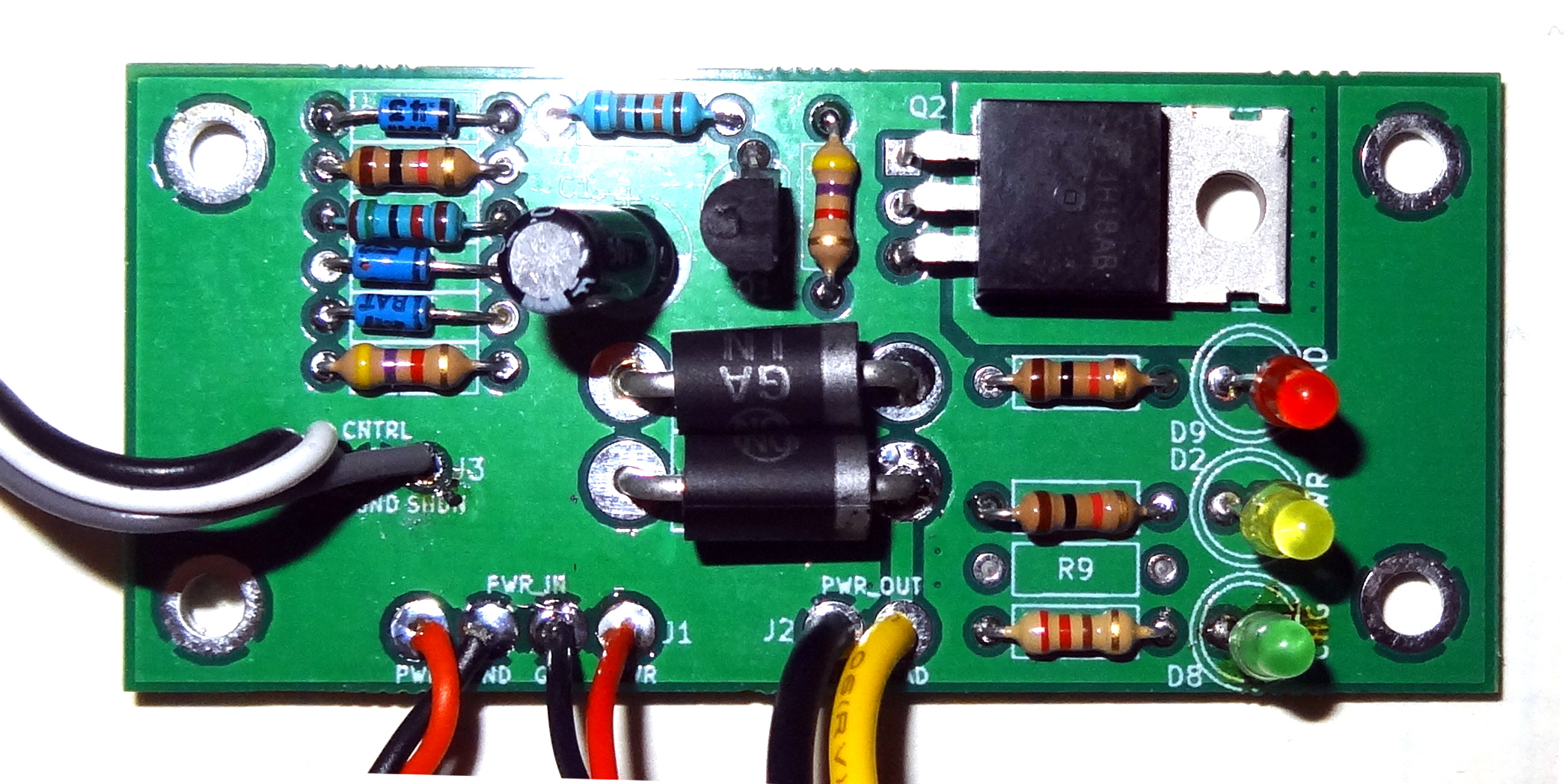
Custom made PC boards
PC boards for this project will be made available. Here is a photo of the bare and populated board, as well as a typical wiring setup.
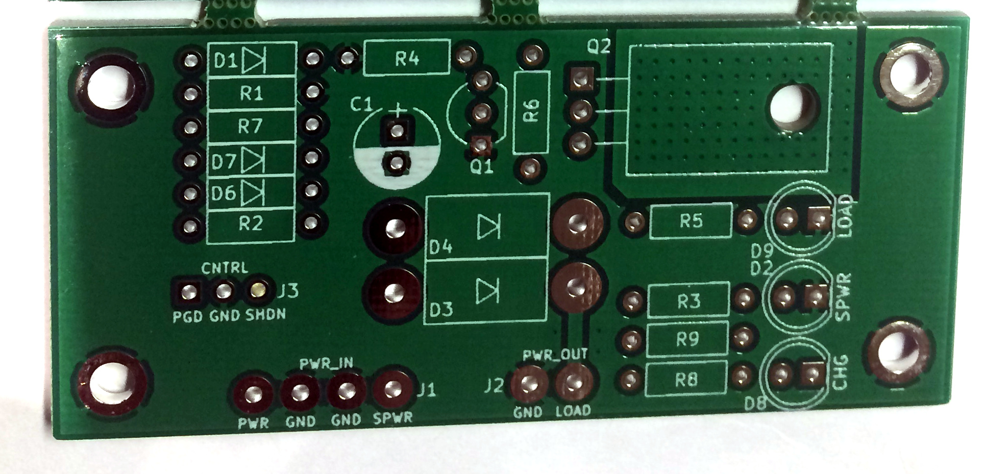
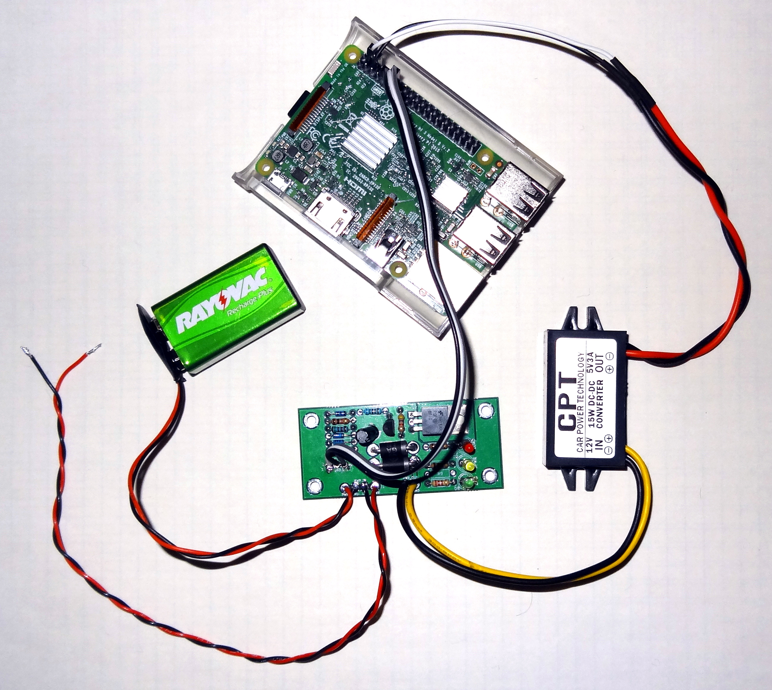
This is a typical power arrangement. +12V is applied to the input leads and the Pi powers and boots.
Upon removing the input power the Pi runs from the Battery and starts its shutdown sequence.
The radio (Baofeng 888 and USB FOB not shown) would also be powered from the 5V 3A power module.
This page will be updated as we do more testing and have more user input. Questions can be directed to the arm-allstar email list.
- Detailed schematic for the power down controller board
- 12V 1300mAhr NiMH battery pack
- Rayovac 9V NiMH Battery
© 2017 - WA3DSP