Simple GPIO for the BBB
Using USB
Introduction and Purchasing
I was perusing the Adafruit site and came across a new FTDI chip that would make a great USB to GPIO converter. Adafruit is a great place to find all kinds of neat stuff and they have great support. Most all of their boards have extensive howto's and lots of data.
The chip is the FT232H and a very nice board is available from Adafruit for $14.95 -
The board uses a micro USB connector so you can't use the mini to standard cable that comes with the BBB. Search this link for an appropriate cable. Remember to make sure it is micro not mini.
What it does
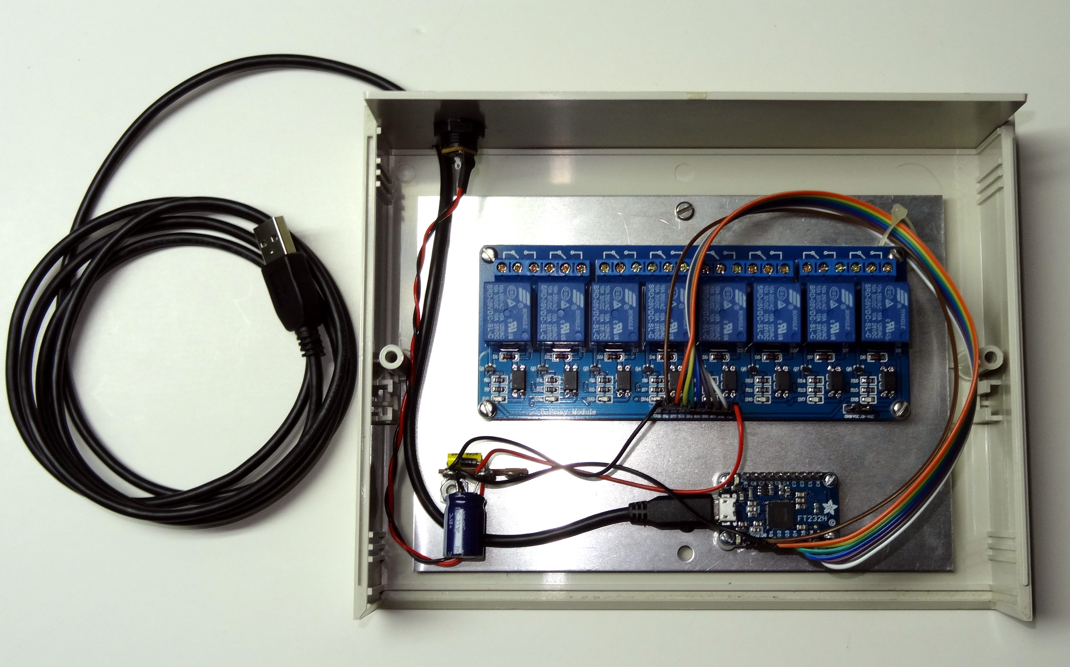
The FT232H is a really nifty chip that allows you to control serial, SPI, IC2, and GPIO ports from USB. I mocked one up and instantly had control of 8 relays. The board supports a total of 16 I/O lines in any combination of input or output. All lines are 3v or 5V capable. The board itself is powered from the USB port it connects to. The USB connector on the board is a micro-USB.
This would be an excellent choice for I/O on the BBB or any computer. It is OS independent and can run on Windows, Mac, Linux, etc. What you monitor or control is up to you. It could be interfaced through Allstar so that DTMF tones could trigger a relay or read a status. The primary programming is done in Python2. In the next section I will show how to add it to the BBB version 1.2.1. I expect it will be part of the next version release.
Setting up the Programming Environment
Refer to the Adafruit site for details on the board. You will find some very good info there.
The specifics for setting up the programming environment on the Adafruit site can be found here -
Refer to this page but keep in mind that the setup is for Ubuntu and there are some minor differences in ArchLinux. There is also a mistake in the Adafruit code listing. Here are the steps for the BBB.
First go to a directory where you can compile and install the code. I suggest /usr/src/utils on the BBB. Then follow these steps. Those in red are what you type in.
Go to a working directory
cd /usr/src/utils
Download needed packages
pacman -Sy  swig cmake confuse
Update GCC
pacman -Sy gcc
Use wget to download the ftdi1 package
wget http://www.intra2net.com/en/developer/libftdi/download/libftdi1-1.1.tar.bz2
untar it
tar xvf libftdi1-1.1.tar.bz2
Enter the ftdi1 directory
cd libftdi1-1.1
mkdir build
cmake -DCMAKE_INSTALL_PREFIX="/usr/" ./
make
make install
Everything should complete, you can ignore the git error.
It will create and install the python2.7 code
cd back to the utils directory
cd ..
wget the Adafruit GPIO library
wget https://github.com/adafruit/Adafruit_Python_GPIO/archive/master.zip
unzip master.zip
cd Adafruit_Python_GPIO-master
Install the libraries
python2 setup.py install

To test if you have working code - enter Python -
python2
Then try importing the libraries
import Adafruit_GPIO
import ftdi1
If all is well there should be no response, just a newline. Type ctrl D to exit Python
Python testing code
Here are a couple of Python code examples to test the bits. The boards has 16 I/O lines - 0 to 7 for D0 to D7, and 8 to 15 for C0 to C7. The first example turns each relay off then on in a constant loop. The second example turns all relays off and the third turns all relays on. In these examples relays 1-8 are connected to D0-D7 on the board (0-7 in Python code). Also remember to type 'python2 [program-name]' on the BBB.
# Turn relays off then on in a loop
# Import standard Python time library.
import time

# Import GPIO and FT232H modules.
import Adafruit_GPIO as GPIO
import Adafruit_GPIO.FT232H as FT232H

# Temporarily disable the built-in FTDI serial driver on Mac & Linux platforms.
FT232H.use_FT232H()

# Create an FT232H object that grabs the first available FT232H device found.
ft232h = FT232H.FT232H()

# Configure digital inputs and outputs using the setup function.
# Note that pin numbers 0 to 15 map to pins D0 to D7 then C0 to C7 on the board.
ft232h.setup(0, GPIO.OUT)
ft232h.setup(1, GPIO.OUT)
ft232h.setup(2, GPIO.OUT)
ft232h.setup(3, GPIO.OUT)
ft232h.setup(4, GPIO.OUT)
ft232h.setup(5, GPIO.OUT)
ft232h.setup(6, GPIO.OUT)
ft232h.setup(7, GPIO.OUT)

print 'Press Ctrl-C to quit'
while True:
 for x in range(0, 8):
    print "Disengaging relay %d" % (x+1)
    ft232h.output(x, GPIO.HIGH)
    time.sleep(1)
 time.sleep(3)
 for x in range(0, 8):
    print "Engaging relay %d" % (x+1)
    ft232h.output(x, GPIO.LOW)
    time.sleep(1)
 time.sleep(3)

# Turn all relays OFF
# Import standard Python time library.
import time

# Import GPIO and FT232H modules.
import Adafruit_GPIO as GPIO
import Adafruit_GPIO.FT232H as FT232H

# Temporarily disable the built-in FTDI serial driver on Mac & Linux platforms.
FT232H.use_FT232H()

# Create an FT232H object that grabs the first available FT232H device found.
ft232h = FT232H.FT232H()

# Configure digital inputs and outputs using the setup function.
# Note that pin numbers 0 to 15 map to pins D0 to D7 then C0 to C7 on the board.
ft232h.setup(0, GPIO.OUT)
ft232h.setup(1, GPIO.OUT)
ft232h.setup(2, GPIO.OUT)
ft232h.setup(3, GPIO.OUT)
ft232h.setup(4, GPIO.OUT)
ft232h.setup(5, GPIO.OUT)
ft232h.setup(6, GPIO.OUT)
ft232h.setup(7, GPIO.OUT)

for x in range(0, 8):
    ft232h.output(x, GPIO.HIGH)


# Turn all relays on
# Import standard Python time library.
import time

# Import GPIO and FT232H modules.
import Adafruit_GPIO as GPIO
import Adafruit_GPIO.FT232H as FT232H

# Temporarily disable the built-in FTDI serial driver on Mac & Linux platforms.
FT232H.use_FT232H()

# Create an FT232H object that grabs the first available FT232H device found.
ft232h = FT232H.FT232H()

# Configure digital inputs and outputs using the setup function.
# Note that pin numbers 0 to 15 map to pins D0 to D7 then C0 to C7 on the board.
ft232h.setup(0, GPIO.OUT)
ft232h.setup(1, GPIO.OUT)
ft232h.setup(2, GPIO.OUT)
ft232h.setup(3, GPIO.OUT)
ft232h.setup(4, GPIO.OUT)
ft232h.setup(5, GPIO.OUT)
ft232h.setup(6, GPIO.OUT)
ft232h.setup(7, GPIO.OUT)

for x in range(0, 8):
    ft232h.output(x, GPIO.LOW)
Making it work with Allstar
Below are example code snippets to make the relays controllable with DTMF entered on an Allstar system. These are just examples. There are many ways to do this and lots more that you could do. I am only showing output driving 8 relays. There is also code to read back 8 input bits from the board. The first two snippets show the server and client programs. The server initializes the board and runs in the background awaiting commands. It can also send status back to the client. The server runs in the background from boot. The client is run as needed.
# usb_gpio_init.py
#
# This program intializes the FTDI FT232H and waits in the
# background for commands
#
# Now reads input bits
#
# D. Crompton 2/2015
#
import socket
import Adafruit_GPIO as GPIO
import Adafruit_GPIO.FT232H as FT232H

dgramSock = socket.socket( socket.AF_INET, socket.SOCK_DGRAM )
dgramSock.bind( ('', 23000) )

# Temporarily disable the built-in FTDI serial driver on Mac & Linux platforms.
FT232H.use_FT232H()

# Create an FT232H object that grabs the first available FT232H device found.
ft232h = FT232H.FT232H()

# Turn off all relays
# Initialization can be set to any desired state

ft232h.setup(0, GPIO.OUT)
ft232h.output(0, GPIO.HIGH)
ft232h.setup(1, GPIO.OUT)
ft232h.output(1, GPIO.HIGH)
ft232h.setup(2, GPIO.OUT)
ft232h.output(2, GPIO.HIGH)
ft232h.setup(3, GPIO.OUT)
ft232h.output(3, GPIO.HIGH)
ft232h.setup(4, GPIO.OUT)
ft232h.output(4, GPIO.HIGH)
ft232h.setup(5, GPIO.OUT)
ft232h.output(5, GPIO.HIGH)
ft232h.setup(6, GPIO.OUT)
ft232h.output(6, GPIO.HIGH)
ft232h.setup(7, GPIO.OUT)
ft232h.output(7, GPIO.HIGH)

#Setup c0-c7 as inputs

for x in range(8,16):
  ft232h.setup(x, GPIO.IN)

# wait for command and execute

while 1:

  msg, (addr, port) = dgramSock.recvfrom( 100 )
  if msg[0:2] == "AT":
     if msg[2:3].upper()=="R":
       rdbits=""
       for x in range(15,7,-1):
          if ft232h.input(x)==GPIO.LOW:
              rdbits=rdbits+"0"
          else:
              rdbits=rdbits+"1"
       dgramSock.sendto( rdbits, (addr, port) )
     elif msg[2:4].isdigit():
       if (int(msg[2:3])<1 or int(msg[2:3])>8):
         dgramSock.sendto( "invalid relay", (addr, port) )
       elif (int(msg[3:4])<0 or int(msg[3:4])>1):
         dgramSock.sendto( "invalid state", (addr, port) )
       else:
         relay=int(msg[2:3])-1
         if msg[3:4]=="0":
            dgramSock.sendto( "Relay "+str(relay+1)+" OFF", (addr, port) )
            ft232h.output(relay, GPIO.HIGH)
         if msg[3:4]=="1":
            dgramSock.sendto( "Relay "+str(relay+1)+" ON", (addr, port) )
            ft232h.output(relay, GPIO.LOW)
     else:
       dgramSock.sendto( "no match", (addr, port) )
  else:
     dgramSock.sendto( "invalid", (addr, port) )
Now the client program. It takes two arguments for setting relays, the relay number 1-8 and the state for the selected relay 0|1 - Use the single argument 'r' to read back the input bits.
# usb_gpio_client.py
#
# This program take two parameters, Relay and state
# Relay is 1-8 and state is 0|1
# Can be run at the Linux command line or via Allstar
# Added bit input readback. Use 'r' as parameter to
# read bits.
#
# D. Crompton 2/2015

import socket
import sys

def testbit( value ):
   bit=["1","2","4","8","16","32","64","128"]
   y=1
   for x in(bit):
       if int(x)&int(value,2):
           print "Bit ",y," = 1"
       else:
           print "Bit ",y," = 0"
       y=y+1
   return

# Test for running server
output = commands.getoutput('ps ax')
if not 'usb_gpio_init' in output:
    print "Server not running"
    exit()

msg=""
for x in range(1,len(sys.argv)):
   msg=msg+sys.argv[x]

dgramSock = socket.socket( socket.AF_INET, socket.SOCK_DGRAM )

# port can be changed - must match server - usb_gpio_init.py

dgramSock.sendto( "AT"+msg, ('', 23000) )
result=dgramSock.recv( 100 )
if msg[0:1].upper()=="R":
   print
   print "Decimal -",int(result,2)
   print "Binary -",result
   print
   testbit(result)
else:
   print result
dgramSock.close()
Running the Code
Start the server in the background - python2 usb_gpio_init.py & - Running the client at the command line produces this output:
python2 usb_gpio_client.py 1 1
Relay 1 ON

python2 usb_gpio_client.py 1 0
Relay 1 OFF

python2 usb_gpio_client.py 0 0
invalid relay

python2 usb_gpio_client.py 9 0
invalid relay

python2 usb_gpio_client.py 8 2
invalid state

python2 usb_gpio_client.py 8 1
Relay 8 ON

python2 usb_gpio_client.py 8 0
Relay 8 OFF

python2 usb_gpio_client.py r

Decimal - 255
Binary - 11111111

Bit  1  = 1
Bit  2  = 1
Bit  3  = 1
Bit  4  = 1
Bit  5  = 1
Bit  6  = 1
Bit  7  = 1
Bit  8  = 1

python2 usb_gpio_client.py r

Decimal - 254
Binary - 11111110

Bit  1  = 0
Bit  2  = 1
Bit  3  = 1
Bit  4  = 1
Bit  5  = 1
Bit  6  = 1
Bit  7  = 1
Bit  8  = 1
The code in rpt.conf to turn the relays on and off. *871-878 turns relays 1-8 on and *881-*888 turns relays 1-8 off. Full paths are probably not necessary here if they are in the search path but it doesn't hurt to include them.
[functions]
871=cmd,/usr/bin/python2 /usr/local/sbin/usb_gpio_client.py 1 1
872=cmd,/usr/bin/python2 /usr/local/sbin/usb_gpio_client.py 2 1
873=cmd,/usr/bin/python2 /usr/local/sbin/usb_gpio_client.py 3 1
874=cmd,/usr/bin/python2 /usr/local/sbin/usb_gpio_client.py 4 1
875=cmd,/usr/bin/python2 /usr/local/sbin/usb_gpio_client.py 5 1
876=cmd,/usr/bin/python2 /usr/local/sbin/usb_gpio_client.py 6 1
877=cmd,/usr/bin/python2 /usr/local/sbin/usb_gpio_client.py 7 1
878=cmd,/usr/bin/python2 /usr/local/sbin/usb_gpio_client.py 8 1

881=cmd,/usr/bin/python2 /usr/local/sbin/usb_gpio_client.py 1 0
882=cmd,/usr/bin/python2 /usr/local/sbin/usb_gpio_client.py 2 0
883=cmd,/usr/bin/python2 /usr/local/sbin/usb_gpio_client.py 3 0
884=cmd,/usr/bin/python2 /usr/local/sbin/usb_gpio_client.py 4 0
885=cmd,/usr/bin/python2 /usr/local/sbin/usb_gpio_client.py 5 0
886=cmd,/usr/bin/python2 /usr/local/sbin/usb_gpio_client.py 6 0
887=cmd,/usr/bin/python2 /usr/local/sbin/usb_gpio_client.py 7 0
888=cmd,/usr/bin/python2 /usr/local/sbin/usb_gpio_client.py 8 0
Here I show how to turn multiple relays on or off with macros. *52 would turn on all odd numbered relays, *53 would turn them off, *54 would turn on all even mumbered relays, *55 would turn them off.
[macro]
2=*871 *873 *875 *877#
3=*881 *883 *885 *887#
4=*872 *874 *876 *878#
5=*882 *884 *886 *888#
Conclusion
So as you can see this makes a very simple and clean way to control I/O bits on the BBB or any computer. Below is a link to the 8 relay opto-isolated board from Amazon. It is $9.99 with free shipping. You can get boards cheaper directly from China but you would wait a lot longer to get them. If you need 8 output controls this is a good price and it is a well made board.
I know some seem to have a problem with using USB but it is one of the primary ways we interface with computers and unlike in it's early days it now works very well. When using a good USB hub on the BBB you can connect and use multiple USB devices with ease. But beware not all USB hubs are created equal. There is a lot of junk out there. If you are having a problem with USB suspect the hub. I highly recommend the Belkin F4U040. I am sure there are others that will work but if you are having problems eliminate the hub and plug directly into the BBB to see if it clears up. This would be even more apparent on USB audio. When it works it works well, when it doesn't you will know it.
Check the Adafruit site for links to data sheets and more info on using the FT232H.
© 2015 - WA3DSP